Firmware Architecture
ECU A, B, C and D share a common architecture, with the exception that ECU A also has USB enabled. On this page, we detail the architecture of the firmware for each ECU, starting with the simpler ECU B, C, and D.
ECU B, C, and D
Firmware of ECU B, C and D contains six tasks:
The CAN Receive Task, which receives and processes CAN messages through a Stream Buffer filled by the CAN-FD peripheral Interrupt Service Routine (ISR).
The Diag RX Task, which receives and processes full (reconstructed) diagnostic messages through a Stream Buffer filled by the CAN Receive Task.
The main Periodic Task, which is executed periodically at a specified interval (typically, 10ms). It is responsible for updating various modules of the firmware. Periodic CAN message transmissions are requested by this task.
The Diag TX Task, which is responsible for fragmenting and sending diagnostic answers, with specified Flow Control settings.
The CAN Send Task, which is responsible for sending CAN messages requested through a Stream Buffer. Messages may be requested by any other task that needs to communicate over CAN.
The Error Handling Task, which is woken up when an error needs to be processed and reported.
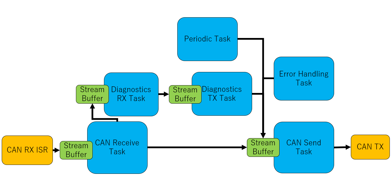
Architecture of firmware of ECU B, C, and D.
ECU A
Firmware of ECU A is identical to ECU B, C, and D, but with two additional tasks:
The USB Receive Task, which receives USB commands and processes them
The USB Send Task, which sends requested data (again, through a Stream Buffer) over USB.
With ECU A, diagnostic commands may also be sent over USB instead of CAN.
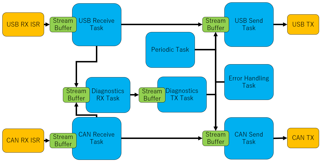
Architecture of firmware of ECU A.
Additional Tasks
In recent versions, new tasks have been added to allow users to easily implement their custom tasks. ECU A can (optionally) use these tasks to implement a gs_usb (candlelight) device.