Hardware
This page gives details about RAMN’s hardware.
Overview
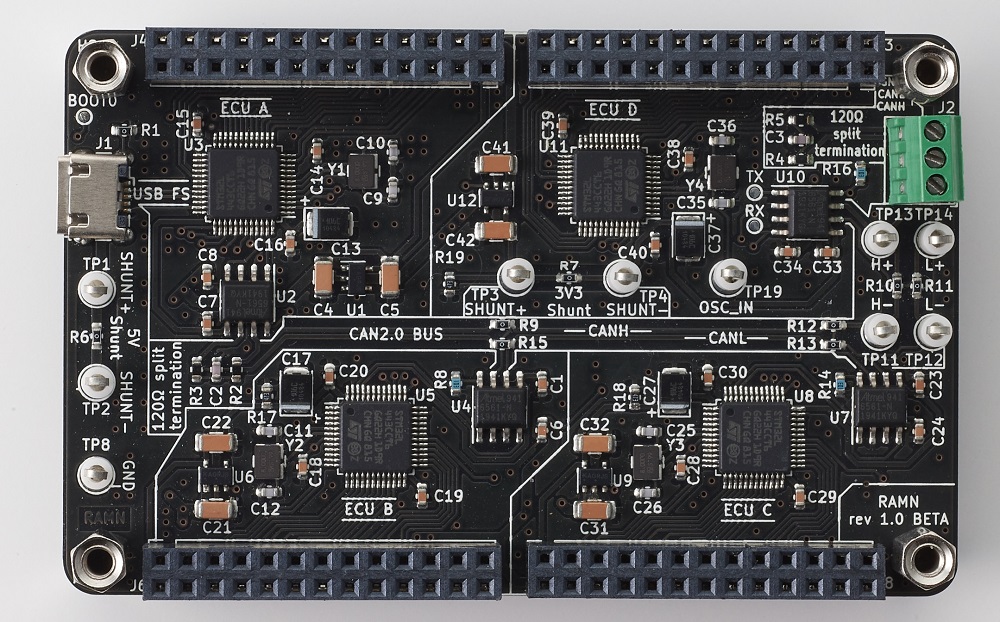
RAMN’s main board is a credit-card size PCB with 4 ECUs, a CAN FD bus and a USB port.

Main board of RAMN
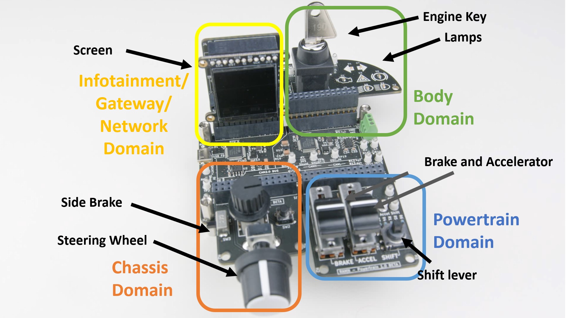
RAMN’s main board can be expanded with expansions boards to add features such as sensors and actuators.

Simple setup of RAMN with 4 expansions: SCREENS (GATEWAY), CHASSIS, POWERTRAIN, BODY.
ECUs (Electronic Control Units)
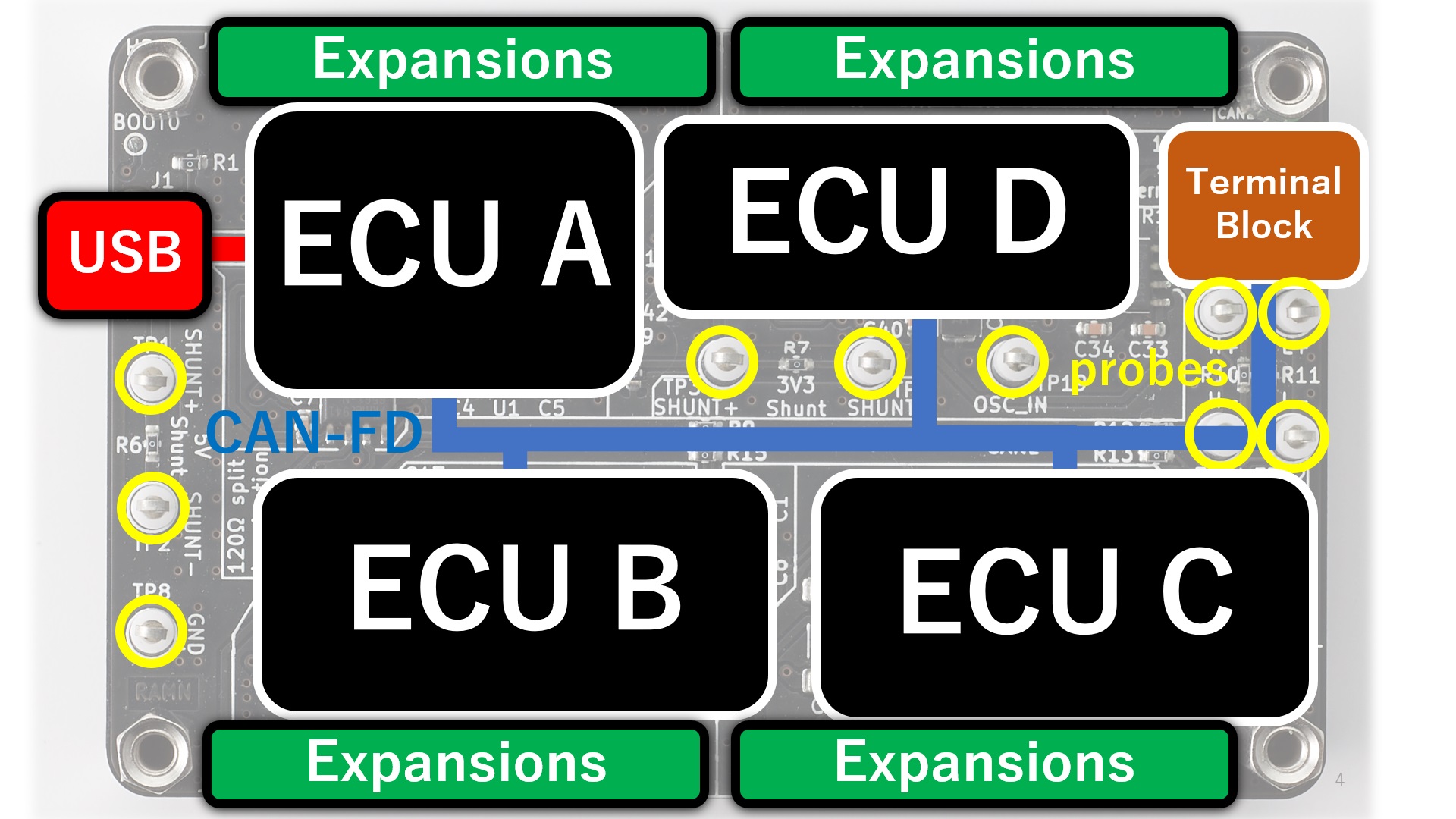
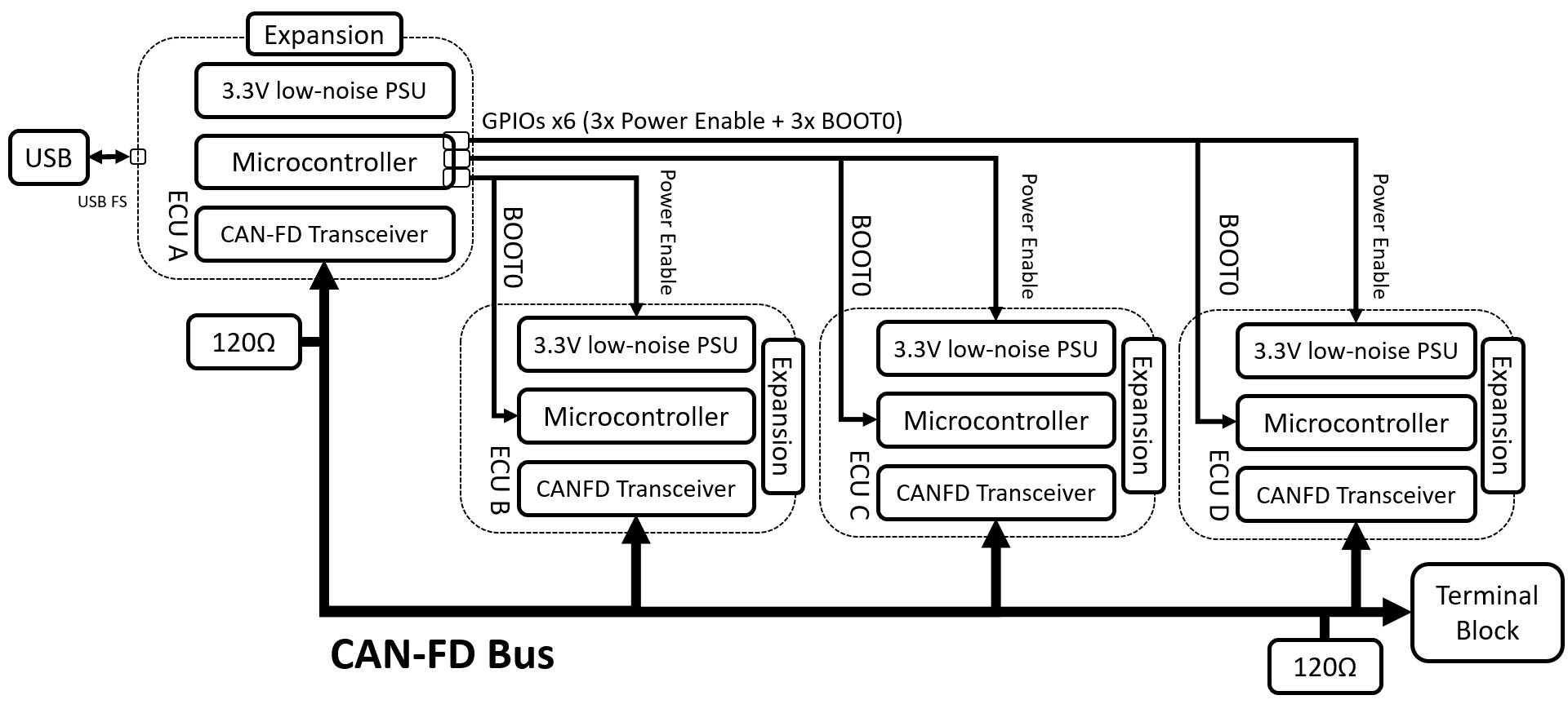
There are 4 ECUs on RAMN (ECU A, ECU B, ECU C, and ECU D), and they all share a common design:
ECU A additionally features a USB connection. The USB port is the main 5V power supply for the whole board, and is also used as a mean to reprogram all ECUs. ECU A has 6 GPIOs that are used to control:
The power supply of ECU B, ECU C, and ECU D
The boot mode (BOOT0 pin) of ECU B, ECU C, and ECU D
ECU D has an additional shunt resistor and clip-on probes for easier measurements.
CAN FD bus
RAMN features a CAN FD bus that connects the 4 ECUs and is terminated on both side by 120ohm split-terminations.
The CAN FD bus features shunt resistors and clip-on probes for easier measurements as well.
The CAN FD bus can be accessed from outside through a terminal block.
Block Diagrams

Simple Block diagram of RAMN’s main board.

Block Diagram of RAMN showing connection between ECUs.
Schematics Details
RAMN:
Expansions: