Customization Guide
This page contains information on how to customize RAMN, and guidance on implementing some projects (e.g., adding a custom bootloader, adding message authentication, etc.). If you want to learn what you can do with the default firmware, check the Quick Start Guide or User Guide.
Summary:
All ECUs share the same source code, only their configurations differ (either
#define TARGET_ECUA,#define TARGET_ECUB,#define TARGET_ECUC, or#define TARGET_ECUD).ramn_config.hholds the current configuration,ramn_customize.cprovides hooks to common functions (e.g., a function that is called when a CAN message is received).When you add new CAN identifiers to the network, you need to update CAN filters (both standard and extended), or disable filters entirely.
CAN peripherals are configured in CAN-FD mode but only use classic CAN messages. You can change the default traffic to CAN-FD, following instructions on this page.
You have a total of 256kB RAM, and either 256kB or 512kB Flash. If you run out of memory, you can reduce the size of CAN and USB buffers, enable compiler optimizations, or remove unused features (in
ramn_config.h).If you use STM32 code generation (i.e., if you modify
RAMNV1.ioc) be careful not to let it overwrite your own code.
RAMN is a regular STM32 project made with STM32CubeIDE, and based on HAL and FreeRTOS, for STM32L552 and STM32L562 microcontrollers. If you need information not present on this page, you can always search the Internet for general STM32, HAL, and FreeRTOS resources.
Content:
Modifying RAMN Firmware
The RAMN firmware is built using the GCC toolchain. Although you are free to use any IDE you like, it is recommended that you install the most recent STM32CubeIDE from STMicroelectronics’ website.
You can download RAMN’s source code from the Github repository (click “Code” then “Download ZIP”). The source code is in the firmware/RAMNV1 folder.
After installing STM32CubeIDE, open it, create or open a workspace, then select “File” > “Import…” > “Existing Projects into Workspace”, then select the path where firmware/RAMNV1 is located. Click “Next”, then import the project with the default settings by clicking “Finish”.
This will make the RAMN project available in your workspace. The source code is the same for all ECUs:
ECU A firmware is built with the
TARGET_ECUAflag.ECU B firmware is built with the
TARGET_ECUBflag.ECU C firmware is built with the
TARGET_ECUCflag.ECU D firmware is built with the
TARGET_ECUDflag.
You can change the default target ECU by modifying ramn_config.h and replacing #define TARGET_ECUA with your target.
When you modify the source code, the modifications will apply to all ECUs.
To write code specific to a single ECU, use #ifdef and endif preprocessor directives around it.
For example, to apply modifications only to ECU A:
#ifdef TARGET_ECUA
// Code executed by ECU A
#else
// Code executed by ECU B, C, and D
#endif
Alternatively, you can maintain four separate copies of the source code, allowing each ECU to have its own independent source code and reducing the risk of accidental modifications.
To build the firmware for the default target ECU that you defined in ramn_config.h, select “Project” > “Build Project”, or press the hammer icon.
Firmware binary files (.elf, .bin, .hex), as well as debug information files (.list, .map), will be located in the RAMNV1/Debug folder.
Useful shortcuts:
Use Control+H to search for strings (e.g., variables and functions mentioned in this page).
Use Control+Tab to switch between source files and header files.
Press Control and click a function name to go to its definition.
Press Alt+Left to go back.
To find where a variable or function is used, right click on it and select “References” > “Project”.
Warning
When changing the target ECU, STM32CubeIDE may take time to update references and may have trouble searching the project. To avoid this issue, after changing the target ECU, you should select “Project” > “C/C++ Index” > “Rebuild”.
To build the firmware for all ECUs at once, you can use the build scripts in the scripts/build folder (make sure that STM32CubeIDE is closed first). You may need to update STM32CUBEIDEPATH in the build scripts (in ``_version.bat`` or ``_version.sh``) to match your installation.
BUILD_Clean_Debug.bat will build the firmware for all four ECUs, and put the new firmware files in the scripts/firmware folder.
Warning
Default RAMN is optimized to use most of the available memory. If your application requires significant memory usage, you may encounter:
“region XX overflowed by YY bytes” error when building the project.
callocreturning NULL.Stack overflows in FreeRTOS tasks.
You can easily free memory for your application by reducing USB and CAN buffer sizes. Read the Understanding RAMN’s Memory section to learn how to free more memory for your application.
Note
RAMN is configured by default to support memory protection. If your application requires strict memory protection (e.g., because you want to use RAMN for a Capture The Flag event where participants must not be able to dump memory), read the Understanding RAMN’s Security Features section.
If memory protection isn’t a concern (e.g., because you are using RAMN as a research or education platform), you can replace the content of STM32L5_FLASH.ld with the content of STM32L5_FLASH_INSECURE.ld (in RAMNV1 folder) to free more memory for your application.
Flashing RAMN Firmware
There are many interfaces available to flash a new firmware. The fastest and easiest to use is the STM32 embedded bootloader interface (which can reprogram ECU A using DFU over USB, and ECU B/C/D over CAN-FD through ECU A).
The scripts ProgramECU_A.bat and ProgramECU_BCD.bat located in scripts/STbootloader/windows can be used to flash the firmware .hex files (ECUA.hex, ECUB.hex, ECUC.hex, and ECUD.hex) located in the scripts/firmware folder.
See Flashing Scripts for more details.
Debugging RAMN Firmware
To debug the source code of a RAMN ECU, you need to purchase an external JTAG debugger and connect it to the ECU that you want to debug. You can find details in the JTAG Hardware Interface section (STM32CubeIDE can also flash ECUs, so you do not need to use STM32CubeProgrammer).
First, make sure that you have defined the target ECU that you want to debug in ramn_config.h.
Connect a debugger to that ECU, and press the green bug icon in STM32CubeIDE (or select “Run” > “Debug”).
If it is the first time that you run the debugger, you may see a prompt, for which you should keep the default settings.
If debugging fails (or is unreliable), try deleting RAMNV1 Debug.cfg and RAMNV1 Debug.launch to force the creation of a fresh debug configuration.
Then, select “Run” > “Debug Configurations…”, select the “Debugger” tab, and experiment with different settings (try different “Debug probe” settings, and try both SWD and JTAG).
Also make sure that C/C++ Application in the Main tab points to the .elf file of your current configuration (typically, Debug/RAMNV1.elf). You can use the “Search Project…” button to identify the correct binary file.
If possible, try to enable RTOS Kernel Awareness (Enable “RTOS proxy”, Driver: “FreeRTOS”, Port: “ARM_CM33_NTZ”) to get more debugging information, but turn it off if you encounter debugging issues.
STM32CubeIDE will automatically reflash the ECU connected via JTAG during debugging. However, it cannot reflash other ECUs. If your modifications impact all ECUs (e.g., changing the CAN baud rate), you need to use the flashing scripts to make sure all ECUs take into account your modifications.
Configuring the Firmware (ramn_config.h)
You can configure the firmware by editing ramn_config.h in the Core/Inc folder.
As explained earlier, this file defines the target ECU for debugging or building the firmware in STM32CubeIDE.
Read the comments in ramn_config.h and adjust the settings to match your needs.
Key configuration options include:
ENABLE_USB_DEBUG: Enables additional debug output over USB (e.g., human-readable CAN errors).LED_TEST_DURATION_MS: Set to 0 to skip ECU D’s LED test at startup.WATCHDOG_ENABLE: Enables a watchdog timer to reset RAMN if its main periodic task crashes.AUTO_RECOVER_BUSOFF: Resets the CAN/CAN-FD peripheral if the ECU enters bus-off mode.HANG_ON_ERRORS: Forces an infinite loop on some non-critical errors (instead of ignoring them).
You may also want to adjust timeout values such as ISOTP_TX_TIMEOUT_MS or UDS_SESSION_TIMEOUT_MS to either match real-world conditions or make the ECU easier to interact with.
For example, UDS_SESSION_TIMEOUT_MS is set to 5000, which forces the ECU to revert to the UDS default session if no request is received for more than 5 seconds during an extended diagnostics session.
If you increase this value, it will be easier for the user to experiment with UDS, but it will not be representative of real ECUs (which require periodic “Tester Present” requests).
Simple Modifications to CAN Traffic (Identifiers, Periods, etc.)
RAMN typically uses two types of CAN messages: “commands” and “controls”. Command messages are sent by an external ECU/computer to request an ECU to apply a specific value to its actuators (e.g., CARLA can use this to request ECU C to accelerate). Control messages report the actual values of the controls applied (e.g., the actual accelerator position applied by ECU C).
For example, if CARLA wants the vehicle to apply a 100% accelerator value, it can send a request to ECU C using the accelerator command message. ECU C may decide to apply 100% accelerator based on this message. However, if ECU C detects that the current speed exceeds a certain threshold or the brake pedal is pressed, it can choose to ignore the command and apply 0% accelerator instead. This approach can be used to implement various closed-loop control algorithms (For example, to implement PID and bang-bang controllers).
You can modify ramn_vehicle_specific.h to update the basic properties of RAMN’s CAN traffic.
For instance, if you want to use ID 0x25 instead of 0x24 to represent the brake control message, change DID_CONTROL_BRAKE from 0x24 to 0x25 (the default-mode 11-bit CAN IDs are the DID_* constants there; per-message period/format/offsets live in the traffic profile catalogs in ramn_traffic_profiles.c).
Upgrading to CAN-FD
You can upgrade from CAN to CAN-FD by modifying ramn_vehicle_specific.h:
Change
CAN_MAX_PAYLOAD_SIZE_DEFAULTto64(to enable 64-byte payloads).Change
CAN_SIM_FORMAT_DEFAULTtoFDCAN_FD_CAN.Change
CAN_SIM_BRS_DEFAULTtoFDCAN_BRS_ON(if you want to enable bitrate switching).
Warning
Changing CAN_MAX_PAYLOAD_SIZE_DEFAULT will likely result in a RAM overflow error when compiling. Read the Understanding RAMN’s Memory section to learn how to free more memory for your application.
Warning
When you update the default traffic to CAN-FD, you will lose compatibility with most slcan tools. It is recommended to use an external CAN-FD adapter. On Linux, you can use the scripts in scripts/vcand to generate a virtual CAN-FD interface from RAMN’s slcan interface.
Advanced Modifications to CAN Traffic (Payload Format, etc.)
ramn_dbc.c is a module used to maintain a database of the most recent values of incoming CAN/CAN-FD messages.
This ensures that all ECUs have access to all RAMN controls, even if a control belongs to another ECU.
For example, if you want to know the status of ECU C’s joystick from ECU A, you can simply read the value of RAMN_DBC_Handle.joystick.
The function
RAMN_ACTUATORS_ApplyControlsinramn_actuators.cis responsible for determining the payload to set for outgoing periodic CAN/CAN-FD messages.The function
RAMN_DBC_FormatDefaultPeriodicMessageinramn_dbc.cformats the message by adding a counter and a CRC32 checksum. The position of these fields is defined per message in the traffic profile catalogs inramn_traffic_profiles.c(usingcounterOffsetandcrcOffset). Setting these offsets to -1 will disable the corresponding field for that message.The function
RAMN_DBC_Sendactually transmits the CAN messages.The function
RAMN_DBC_ProcessCANMessageinterprets and records incoming CAN messages in the RAMN_DBC module.
If you want an ECU to stop sending messages, simply comment out the call to RAMN_DBC_Send.
Traffic Modes (Default vs. J1939)
RAMN can emulate two different CAN traffic specifications (“traffic profiles”):
Default mode: RAMN-native signals on 11-bit identifiers (the
DID_*constants inramn_vehicle_specific.h), with a freshness counter and a CRC32 checksum in each periodic message.J1939 mode: the same signals encoded as SAE J1939 SPNs on 29-bit identifiers (PGN-based), without counters and checksums. Unused payload bytes carry the J1939 “Not Available” pattern (0xFF). This mode also activates the reactive J1939 transport in
ramn_j1939.c(Address Claim, ECU ID over TP, DM1).
Both profiles are always compiled into the firmware. Each profile bundles a signal codec table (ramn_can_database.c), the per-ECU periodic TX catalog, and the RX decode map (both in ramn_traffic_profiles.c); the active profile is designated by a single pointer (g_trafficProfile).
DEFAULT_TRAFFIC_MODE in ramn_config.h (TRAFFIC_MODE_DEFAULT or TRAFFIC_MODE_J1939) only selects the profile active at power-on.
The active profile can also be switched live, without reflashing or rebooting:
Type
trafficmode <default|j1939>in ECU A’s USB CLI. ECU A switches itself, then broadcasts the same request to ECU B, C, and D over UDS functional addressing (CAN ID 0x7DF).trafficmodewithout an argument reports ECU A’s active mode.Individual ECUs can be switched with UDS RoutineControl routine
0x0224(startRoutine, one option byte:0x00for default,0x01for J1939), e.g. payload31 01 02 24 01to switch to J1939 mode. This is the same routine thetrafficmodecommand broadcasts.
Diagnostic protocols (UDS/KWP2000/XCP) accept both their standard 11-bit identifiers and J1939 (PF 0xDA/0xDB) addressing at all times, independently of the active traffic profile, so ECUs remain diagnosable (and switchable back) in either mode.
Standard vs. J1939 Message Mapping
The signal distribution changes depending on the active traffic profile:
Signal |
Source ECU |
Target |
Standard Mode (11-bit ID) |
J1939 Mode (29-bit ID / PGN) |
|---|---|---|---|---|
Command_Brake |
ECU A |
ECU C |
ID |
PGN |
Command_Accel |
ECU A |
ECU C |
ID |
PGN |
Command_Steer |
ECU A |
ECU B |
ID |
PGN |
Command_Shift |
ECU A |
ECU C |
ID |
PGN |
Command_Horn |
ECU A |
ECU C |
ID |
PGN |
Control_Horn |
ECU C |
ECU D |
ID |
PGN |
Command_P-Brake |
ECU A |
ECU B |
ID |
PGN |
Status_RPM |
ECU A |
All |
ID |
PGN |
Note
In J1939 mode, the horn signals are strictly unicast to their respective targets (DA 90 for the command, DA 33 for the status) using Proprietary A. In Standard mode, these are broadcasted using functional IDs.
See Implementing a Secure CAN bus (SecOC, etc.) for a customization example.
Note
ECU A also uses RAMN_DBC_ProcessUSBBuffer to convert USB data received from CARLA into CAN messages.
Modifying CAN Filters or Baud Rate
If you want to add new CAN messages to the traffic specifications (instead of just modifying existing ones), you must ensure that the new CAN identifiers are not filtered. You can do this by:
Commenting out
USE_HARDWARE_CAN_FILTERSinramn_config.h. This disables hardware filters, which slightly increases CPU load.Alternatively, add your new identifiers in
recvStdCANIDListandrecvExtCANIDListinramn_canfd.c, separately for standard and extended identifiers.
If you want to modify the default baud rate, you should modify the CAN/CAN-FD peripheral settings in the RAMNV1.ioc file, as explained in the Modifying the .ioc File section.
Refer to the Bit Timings section if you are not familiar with bit timings.
Alternatively, you can override the default nominal baud rate by modifying FDCAN_Config in ramn_canfd.c to call RAMN_FDCAN_UpdateBaudrate with your new baud rate before initializing the peripheral.
Note
If you only want to temporarily change the baud rate, you do not need to modify the firmware, you can simply use UDS (Interacting with UDS) and USB commands (Interacting with USB).
Modifying the UDS Interface
If you want to customize the UDS interface (either to modify an existing service or add a new one), you need to update the ramn_uds.c file.
You should modify RAMN_UDS_ProcessDiagPayload for physical addressing and/or RAMN_UDS_ProcessDiagPayloadFunctional for functional addressing (if needed).
Be aware that functional addressing is only valid for Single-Frame messages, as per the standard specifications.
If you need to execute your code after the answer is sent (e.g., because the ECU will reset or change baud rate and needs to answer first), send a positive response in the processing function, and perform the actual operation in RAMN_UDS_PerformPostAnswerActions.
Adding New Content
ramn_customize.c is a module designed to make it easier to add custom content to RAMN.
This is the module you should use if you want to build on top of RAMN, without changing its default behavior.
There are various functions in ramn_customize.c that allow you to add your own code in different tasks. For example:
RAMN_CUSTOM_Updateis called by RAMN’s main periodic task every 10ms (by default). It is called by the same tasks that handle other periodic processing (e.g., sending out CAN messages, or updating the screen or LEDs).RAMN_CUSTOM_CustomTaskXfunctions are called by unused tasks, parallel to the main periodic task. They can be used to execute something in parallel with the main periodic task.RAMN_CUSTOM_ProcessRxCANMessageis called by RAMN’s CAN receiving task when a new CAN message has been received.RAMN_CUSTOM_ProcessCDCLineis called by RAMN’s USB receiving task when a new line has been received over USB serial (CDC).RAMN_CUSTOM_TIM6ISRis called by a periodic timer (by default, every second). This can be used to execute something with accurate timing, independent of FreeRTOS.RAMN_CUSTOM_ReceiveUARTis called when a UART command line has been received.RAMN_CUSTOM_ReceiveI2CandRAMN_CUSTOM_PrepareTransmitDataI2Care called when an I2C RX or TX command has been received (RAMN ECU in device mode).
You can also use TIM16 to access a high-accuracy free-running timer, which is not used by other modules (see comments in ramn_customize.c).
You can modify TIM6 and TIM16 without impacting RAMN features.
ECU A’s bitbang module actively uses TIM2 and TIM17 as timers when it is used.
You can disable the bitbang module of ECU A (comment out ENABLE_BITBANG in ramn_config.h) if you want to use these timers in your code.
Read ramn_customize.c for examples, e.g., how to send CAN messages.
Warning
SPI functions (used to update ECU A’s screen) can only be called from the same task, which by default is the main periodic task that calls RAMN_CUSTOM_Update.
This is because the task waits for a transfer-complete notification from the SPI module before resuming execution, but if you call it from another task, that task will not get the notification.
If you want to use SPI from another task, you need to update the calls to RAMN_SPI_Init or RAMN_SCREENMANAGER_Init to make the SPI module notify your task instead.
Example: Send a CAN Message Every Second
To make ECU B transmit every second a classic CAN message with standard ID 0x123 and payload of eight times 0x77, you can add the following code in RAMN_CUSTOM_Update, just after the “Code here is executed every 1s” comment:
#ifdef TARGET_ECUB
FDCAN_TxHeaderTypeDef header;
uint8_t data[8U];

// CAN message header content
header.BitRateSwitch = FDCAN_BRS_OFF; // Bitrate switching OFF (only needed for CAN-FD, but set anyway); other option is FDCAN_BRS_ON.
header.ErrorStateIndicator = FDCAN_ESI_ACTIVE; // ESI bit (for CAN-FD only, but set anyway); other option is FDCAN_ESI_PASSIVE.
header.FDFormat = FDCAN_CLASSIC_CAN; // Classic CAN; other option is FDCAN_FD_CAN.
header.TxFrameType = FDCAN_DATA_FRAME; // Data frame; other option is FDCAN_REMOTE_FRAME, only for classic CAN.
header.IdType = FDCAN_STANDARD_ID; // Standard identifier; other option is FDCAN_EXTENDED_ID for extended.
header.Identifier = 0x123; // Identifier.
header.DataLength = 8U; // DLC (Payload size).

// CAN message payload content
RAMN_memset(data, 0x77, 8U); // write 0x77 8 times

// Send message
RAMN_FDCAN_SendMessage(&header,data);
#endif
Example: Execute Something on Specific CAN Message Reception
To make ECU C execute something on the reception of the CAN message above, you can add the following code in RAMN_CUSTOM_ProcessRxCANMessage:
#ifdef TARGET_ECUC
// Fields that you may want to use:
// pHeader->Identifier: (11-bit val for standard, 29-bit for extended)
// pHeader->IdType: FDCAN_STANDARD_ID or FDCAN_EXTENDED_ID
// pHeader->RxFrameType:  FDCAN_DATA_FRAME or FDCAN_REMOTE_FRAME
// DataLength: length of CAN payload, FDCAN_DLC_BYTES_0 (0) to FDCAN_DLC_BYTES_8 (8) for CAN, FDCAN_DLC_BYTES_0 (0) to FDCAN_DLC_BYTES_64 (0xF, Not 64) for CAN-FD.
// pHeader->ErrorStateIndicator: For CAN-FD, either FDCAN_ESI_ACTIVE or FDCAN_ESI_PASSIVE
// pHeader->BitRateSwitch: For CAN-FD, either FDCAN_BRS_OFF or FDCAN_BRS_ON
// pHeader->FDFormat: FDCAN_CLASSIC_CAN or FDCAN_FD_CAN

// Add or remove checks as needed.
if( (pHeader->FDFormat == FDCAN_CLASSIC_CAN) && (pHeader->Identifier == 0x123) && (pHeader->RxFrameType == FDCAN_DATA_FRAME) && (pHeader->IdType == FDCAN_STANDARD_ID))
{
        /* Code executed by ECU C on reception of this specific CAN message */
}
#endif
Independently, you must make sure that ECU C does not filter the CAN message.
Either undefine USE_HARDWARE_CAN_FILTERS in ramn_config.h, or add the identifier to recvStdCANIDList in ramn_canfd.c:
static const uint16_t recvStdCANIDList[] =
{

/* List of standard IDs received by ECU */

/* ... */

#ifdef TARGET_ECUC
        0x123,
#endif
};
Example: Make a Decision Based on RAMN Controls
You can read the value of current RAMN controls using:
Variables in
ramn_sensors.hif the ECU has physical access (e.g., ECU C for shift joystick).Variables in
ramn_dbc.hif the ECU does not (e.g., ECU A, B, and D for shift joystick).
For example, if you want ECU C (which is physically connected to the shift joystick) to execute code only when the joystick is released, you can add this condition:
if (RAMN_SENSORS_POWERTRAIN.shiftJoystick == RAMN_SHIFT_RELEASED)
{
        // Your code
}
If you want to apply the same condition to another ECU (ECU A, B, or D), you can add this condition:
if (RAMN_DBC_Handle.joystick == RAMN_SHIFT_RELEASED)
{
        // Your code
}
Note
For the first case, the ECU bases its decision on the physical sensor. Even if users spoof the CAN bus by sending CAN joystick messages, ECU C will not react (because ECU C bases its decision on the physical sensor).
For the second case, the ECU bases its decision on the latest relevant CAN message. If you have not implemented CAN bus protections, users can override controls by spoofing the joystick CAN message.
Customizing ECU A’s Display
ramn_screen_manager.c is a module that handles ECU A’s display, allowing the user to switch between various screens by pressing left and right on the joystick.
If you want to modify available screens, as well as the default screen loaded after boot, modify the content of screens and DEFAULT_SCREEN in ramn_screen_manager.c and ramn_screen_manager.h.
If you want to add a new custom screen, you need to create a RAMNScreen_t structure with function pointers (e.g., Init, DeInit, Update, etc.) to your code.
It is recommended that you create a new module (.c and .h files) and imitate the content of ramn_screen_saver.c and ramn_screen_saver.h, which demonstrate a simple screen capable of reading inputs and updating the screen.
Simply copy-paste the content of these files and replace “screensaver” and “screen_saver” strings with the name of your new screen.
Then, modify the files to implement the behavior that you want, and add your structure to the screens array in ramn_screen_manager.c.
If you want to display an image, you can use the image_to_C.py script in the misc folder to convert an image file to source code that can be added to a .c file (RGB565 array).
Then, use RAMN_SPI_DrawImage with your image to display it (preferably in the Init function that only gets called once, and not the Update function, that is called periodically).
ECU A’s display size is 240x240. The “internal screen” has a size of 236x195 (starting at offset x=2, y=2).
You can use RAMN_SPI_SetScroll or RAMN_SPI_ScrollUp to scroll the display (including images).
Depending on how much of the display you want to scroll, you may want to call RAMN_SCREENUTILS_PrepareScrollScreen() during the Init phase, and call RAMN_SPI_SetScroll(SCREEN_HEADER_SIZE) during the DeInit phase.
The display has a 240x320 display buffer, despite only having a 240x240 display area. This means that if you want to scroll the screen, you need to draw a screen with height 320 (but for which only 240 lines are displayed at once).
Saving Data in Flash Memory
You can use ramn_eeprom.c to save data in the emulated EEPROM (using STM32’s flash memory).
This module allows reading and writing 32-bit values to 16-bit indexes (“addresses”).
Since some of these indexes are used to store DTCs and VIN, you should use indexes higher than DTC_LAST_VALID_ADDRESS (or disable features using them by searching for references to RAMN_EEPROM_Write32).
The EEPROM emulation layer may have compatibility issues with FreeRTOS, so make sure that you always check for errors when using it, and test it in various conditions.
If you encounter frequent errors with the ramn_eeprom.c module, feel free to contact us so that we can investigate them.
If you need more memory than the EEPROM emulation can provide, you can use functions in stm32l5xx_hal_flash.h (comments at the beginning of the file explain how to use it).
Be aware that there are significant limitations to writing flash memory while executing code from it.
Modifying the .ioc File
RAMNV1.ioc is the configuration file for STM32CubeIDE’s code generation.
It defines the microcontroller’s pin configurations, interrupts, peripherals (CAN/CAN-FD, SPI, etc.), and FreeRTOS settings.
You can edit RAMNV1.ioc in STM32CubeIDE, which provides a graphical interface for modifying settings (e.g., adding a new GPIO pin or adjusting a peripheral’s baud rate).
Although it is possible to modify these settings directly in source code (e.g., by editing hlpuart1.Init.baudrate = 115200; in main.c), STM32CubeIDE can automatically detect invalid configurations, which can save debugging time.
Double-click RAMNV1.ioc in the project explorer to open the default tab “Pinout & Configuration”. Select “Project” > “Generate Code” to regenerate code based on your changes, if you are not automatically prompted when saving.
System and Peripheral Settings
Most of the settings can be modified in the “Pinout & Configuration” tab.
You can modify peripheral settings in the “Connectivity” category. For example, select “LPUART1” to modify the default UART baud rate. Select “FDCAN1” to modify the default CAN/CAN-FD settings.
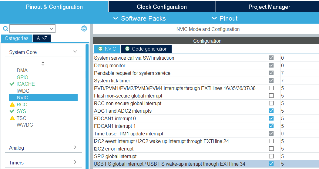
STM32CubeIDE does not enable required interrupts automatically when adding new peripherals. Always check necessary interrupts have been enabled in the NVIC section.
FreeRTOS Settings
FreeRTOS settings are in the “Middleware and Software Packs” > “FreeRTOS” menu (“Config parameters”). There, you can notably modify “Minimal Stack Size” to prevent stack overflow issues, and modify TOTAL_HEAP_SIZE if you need more FreeRTOS heap memory. Note that those settings are different from the main stack and heap sizes described in Linker Settings. If you are not sure which one you should modify, try modifying both.
In the “Config parameters” menu, you can also change the “Memory Management scheme”, which by default is “heap_4”.
Other schemes may not support the free() function, so it is preferable that you do not change it.
If you do not need FreeRTOS runtime stats, you can also disable “GENERATE_RUN_TIME_STATS”, “USE_TRACE_FACILITY” and “USE_STATS_FORMATTING” to optimize your project.
If you do so, you should also disable GENERATE_RUNTIME_STATS in ramn_config.h.
Open the “Tasks and Queues” tab to modify/add/delete FreeRTOS tasks. Double-click a task to modify its settings (the most important settings being the Priority and the Stack Size). Be aware that if you rename a task, STM32CubeIDE will actually delete the code inside that task and generate a new task, so you should copy its content first, then paste it inside the new task after code generation.
Clock Settings
If you want to use the internal clock instead of the external crystal, read the comments at the bottom of ramn_config.h.
To modify the CPU clock (SYSCLK), select the “Clock Configuration” tab (top menu) and modify the PLLCLK N and R parameters. By default RAMN only uses 80MHz, but you can go up to 110MHz. After modifying this clock, make sure to change Q so that PLLQ remains 40MHz.
Since timers rely on SYSCLK, you will also need to modify TIM6 and TIM16 settings if you use them (default RAMN does not require them; they are only preconfigured for your convenience).
Linker Settings
To increase the main stack and main heap sizes (which are different from the FreeRTOS heap and stack sizes described in FreeRTOS Settings), select the “Project Manager” tab (top menu), and update “Minimum Heap Size” and “Minimum Stack Size”.
For other settings, you will need to modify STM32L5_FLASH.ld directly.
Other Tools
You can use the “Tools” tab to use other STM32CubeIDE tools, e.g., to compare your project to another project, or to have an overview of the power consumption of the microcontroller after your changes.
Warning
STM32CubeIDE may delete code when you use the code generation feature.
If you make modifications to automatically generated files (mainly, main.c and main.h), always make them between USER CODE BEGIN ... and USER CODE END ... comments, otherwise they will be deleted.
It is preferable to use a version control system and check for differences when you use the code generation feature, to ensure your code does not get accidentally deleted.
Optimizing Performance
You can use FreeRTOS and STM32CubeIDE tools to optimize your application.
Compiler Optimizations
You can enable compiler optimizations by selecting “Project” > “Properties”, then “C/C++ Build” > “Settings”, then “MCU GCC Compiler” > “Optimization”. There, you can select an optimization level to enable optimizations, favoring speed or size.
FreeRTOS Runtime Stats
On ECU A, you can use the slcan ‘X’ command (see Interacting with USB) to display FreeRTOS runtime stats. You can see the same information in STM32CubeIDE when debugging (Select “Window” > “Show View” > “FreeRTOS” > “Tasks List”):
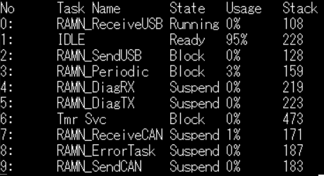
You can see the CPU usage and the lower bound of available stack for each task. Stats are computed from boot time, meaning “Usage” shows the average usage since boot, NOT peak usage. If you want to observe stats under heavy load, reboot and immediately start the heavy processing task.
If CPU usage is high (e.g., due to heavy software algorithms), you may want to increase the CPU clock speed (see Clock Settings) or refactor your code.
“Stack” shows how much memory remains before a task overflows. If this value is close to zero, you need to increase the task’s stack size (see FreeRTOS Settings).
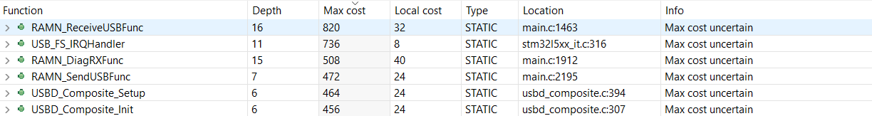
You can use “Window” > “Show View” > “Static Stack Analyzer” to get a better overview of stack usage. (You may need to select “File” > “Refresh” and then click the refresh icon in the Stack Analyzer window to see correct values.) Be aware that some views display sizes in words (32 bits), while others display sizes in bytes (8 bits).
Warning
If you encounter runtime stats issues in STM32CubeIDE, follow the steps here.
FreeRTOS stats are computed using TIM7. If you need better accuracy, you can modify TIM7’s counter period value (e.g., from 7999 to 799), but this will increase CPU load.
Once you are done optimizing your application, you can disable runtime stats (see FreeRTOS Settings).
Note
RAMNV1.ioc was created for STM32L552 microcontrollers.
If you have STM32L562 microcontrollers and want to use their cryptographic hardware peripherals, you must manually update “STM32L552” references to “STM32L562”.
Understanding RAMN’s Memory
Please read Memory Layout, especially if you need memory protection.
If you run out of memory and do not need memory protection, try replacing the content of STM32L5_FLASH.ld with the content of STM32L5_FLASH_INSECURE.ld.
Also try enabling Compiler Optimizations.
If you run out of memory in the INSECURE_RAM region, try reducing the value of the following definitions in ramn_config.h (some definitions may be different for ECU A and for ECU B/C/D):
USB_RX_BUFFER_SIZEUSB_TX_BUFFER_SIZECAN_RX_BUFFER_SIZECAN_TX_BUFFER_SIZEUSB_COMMAND_BUFFER_SIZE
If you run out of memory in the RAM region, you should try reducing heap and stack sizes, as explained in the Modifying the .ioc File section. If you do not know which size to reduce, start with “Minimum Heap Size” (in Linker Settings).
If you use the default STM32L5_FLASH.ld linker script, you can move a variable from RAM to INSECURE_RAM by adding __attribute__ ((section (".buffers"))) to its definition.
If there is a large variable that you consider does not need protection (e.g., non-critical FreeRTOS task stacks), you can move them to INSECURE_RAM and use the freed space for your own application.
Refer to the Implementing Vulnerabilities section if you want to learn how to modify the layout to implement memory vulnerabilities.
Understanding RAMN’s Security Features
Hardening
You can use the HARDENING flag in ramn_config.h to disable features that would easily compromise device security.
When you enable this flag, you will get various compile errors to indicate which other flags you should also enable/disable.
Address them by following prompted recommendations, or by deleting the #error directives.
If you do not need some of the remaining features, remove them by editing the source code directly.
Notably, we recommend that you review available UDS services and edit RAMN_UDS_ProcessDiagPayload and RAMN_UDS_ProcessDiagPayloadFunctional.
Remember to rebuild the index to make sure STM32CubeIDE correctly highlights which functions are still available (Select “Project” > “C/C++ Index” > “Rebuild”).
Memory protection
You can use the MEMORY_AUTOLOCK flag in ramn_config.h to protect memory.
When this flag is enabled, the STM32 RDP option byte will be set during boot to temporarily enable memory protection.
You will not be able to debug the firmware anymore until you remove the protection, so it should be done after you are done debugging it.
To make sure that memory protection is active, you need to ensure that the firmware has been executed at least once (which may not be the case depending on the tool that you used to program the firmware). It is therefore preferable that you remove any JTAG debugger and power-cycle RAMN once.
Using the default protection mechanism (RDP level 1), memory protection can be removed at any time, but memory will be automatically erased.
You can use RDP level 2 (by updating RDP_OPTIONBYTE in ramn_config.h) to permanently lock your device, but you will naturally lose the ability to reflash and debug it.
To remove protection for ECU A, you can use the ‘D’ slcan command. By default, this command requires a “password” that is defined by DFU_COMMAND_STRING.
However, this “password” is only to prevent accidental memory erasure (e.g., because of fuzzing); it is always possible to remove protection over JTAG without any password.
ECU A protection is automatically removed by ECUA_OptionBytes_Reset.bat and ProgramECU_A.bat.
If you changed the password, you need to update the ECUA_goToDFU.py script accordingly.
You can use the Unlock_BCD.bat script to remove memory protection for ECU B/C/D.
Alternatively, you can enable and disable memory protection using the STM32 bootloader interface.
The STM32 bootloader can independently enable/disable read and write protections.
For ECU A, you can use the DFU tool provided by STMicroelectronics (or STM32CubeProgrammer).
For ECU B/C/D, you can use the canboot.py python script in the scripts/STBootloader folder:
# Enable memory read protection for ECU B
python canboot.py AUTO B -rp

# Enable memory write protection for ECU B
python canboot.py AUTO B -wp

# Remove memory read protection for ECU B
python canboot.py AUTO B -ru

# Remove memory write protection for ECU B
python canboot.py AUTO B -wu
If you directly use the STM32 bootloader interface, make sure to use consistent memory protection, or you may run into issues (See Inconsistent Memory Protection).
Read Memory Layout to learn about how memory can (or cannot) be protected by the MEMORY_AUTOLOCK flag. Remember that SRAM1 (INSECURE_RAM region) cannot be protected, unless you permanently lock your device (see RAM).
The following JTAG behavior is expected when RDP level 1 memory protection is active:
Users can connect over JTAG and remove memory protection (triggering a mass memory erase).
Users cannot read/write Flash (will return an error).
Users cannot read/write SRAM2 (”RAM”) (will only show zeroes, without returning an error).
Users can read/write SRAM1 (”INSECURE_RAM”). However, users cannot resume execution.
Users can execute arbitrary code, but that arbitrary code cannot access SRAM2 or Flash.
Unique Hardware Seed
You can use the 8 bytes located at HARDWARE_UNIQUE_ID_ADDRESS if you need a seed for a key derivation function that generates a unique key per ECU.
Additional Security Features (TrustZone, etc.)
STM32L5 microcontrollers have an MPU if you need to enable memory protection.
Although they are disabled by default, you can enable TrustZone features for your application. Refer to the STM32L552 datasheet for more information about STM32L552 security features.
If your RAMN has STM32L562 microcontrollers, you also have access to a cryptographic engine (e.g., for AES and public key operations). Refer to the STM32L562 datasheet for details.
Exploring RAMN’s Security
Analyzing RAMN Firmware in Ghidra
If you want to analyze RAMN firmware in Ghidra, you should use the .elf file that is created in the RAMNV1/Debug or RAMNV1/Release folder when building the firmware. The STM32L552/STM32L562 microcontrollers used by RAMN rely on ARM Cortex M-33 cores, which only support thumb instructions.
Note that changing compiler optimization settings will typically lead to very different binary code.
Contrary to the .hex file, the .elf file has debug symbols, which greatly simplifies analysis.
If you want to remove debug symbols, you need to use the arm toolchain, not the default toolchain that you may have on your system.
For example, you should use arm-none-eabi-strip instead of just strip.
When you load a .hex file in Ghidra, it may struggle to analyze it because it misses information about the memory map.
The firmware’s default start address (Flash) is 0x08000000.
You should open “Tools” > “Memory Map”, and add regions as defined in STM32L5_FLASH.ld.
You can also add information about special registers (e.g., peripherals) based on the STM32L5 reference manual.
Search for Memory map and register boundary addresses and peripheral register boundary.
You can find online resources to help you automate this.
Writing ARM shell code for RAMN
You can write ARM shell code (binary code) that can be executed on RAMN using common shell code writing tools. You must select “ARM (thumb)” as the target (16-bit instructions for ARM Cortex M-33). TrustZone is not used by default, and there is no need for privilege escalation. By default, RAM execution is enabled to allow users to easily test shell code.
You can use UDS Routine 0x209 (see Routine Control (0x31)) to test a payload over CAN.
The diagnostics task will jump to the address of your payload.
This routine requires that you first perform the simple security access method described in Security Access (0x27), to prevent accidental execution during fuzzing.
Because UDS data is directly copied to memory, you must provide instructions in Little Endian (nop should appear as 00BF on your CAN payload, not BF00).
The function will not automatically return, therefore you should save context and safely return yourself, e.g., by executing bx lr (7047) at the end.
The UDS service will only answer if your code successfully returned (the answer comes after payload execution, not before).
For example, payload 00BF7047 will execute a NOP instructions and return.
Writing ARM shell code for RAMN is not particularly difficult, but be aware that most resources online consider Linux embedded systems, not FreeRTOS embedded systems. While most of the techniques are valid, it is not possible for example to “pop a shell” with a syscall on RAMN, since there is no shell. Similarly, be aware that most tasks spend their time sleeping, waiting for a notification to continue. If you exploit a task and call a function that waits for a notification meant for another task, it will hang forever, unless you first overwrite the notification handler or find another way to notify it. Similarly, a task may not check that a resource is available because it expects to be the only one using it, so you may inadvertently impact other tasks.
Debugging with OpenOCD
You can connect OpenOCD debuggers to RAMN’s ECUs. See JTAG Hardware Interface for connections.
You should use the stm32l5x.cfg config file (on Linux, it is typically found somewhere in /usr/share/openocd).
Start an openocd server and connect to it with:
openocd -f <your_debugger.cfg> -f stm32l5x.cfg
nc localhost 4444  # replace 4444 with actual openocd server port
You can then execute debugging commands, e.g:
set_reg {pc 0x08000000}
read_memory 0x200000000 32 100
resume
Guidance for Typical Projects
Preparing RAMN for a Capture The Flag Event (or Similar)
You can follow the instructions on this page to create CTF challenges. For example, you can modify CAN identifiers following the instructions in the Simple Modifications to CAN Traffic (Identifiers, Periods, etc.) section, and have participants guess your new identifiers. You can find examples of both simple and advanced CTF challenges in the CTF Write-ups section.
If you want to use RAMN for Capture The Flag events or similar activities, you need to ensure that users cannot easily read out the firmware or execute arbitrary code. If your CTF targets beginners, you may skip the instructions in this section.
To make sure users cannot easily dump the firmware, you should modify ramn_config.h so that:
HARDENINGis enabled, to remove potentially dangerous features (UDS services to read/write memory, etc.).MEMORY_AUTOLOCKis enabled, to automatically enable STM32 memory protection (RDP) during boot, thus preventing memory dump using JTAG or bootloader mode.
Additionally, consider turning on compiler optimizations to remove unused code that may stay in memory.
You cannot debug your firmware when the MEMORY_AUTOLOCK flag is defined, so you should turn it on only after you are done developing.
Read the Understanding RAMN’s Security Features section to learn more about memory protection.
Remember that MEMORY_AUTOLOCK will only protect the Flash and the SRAM2 (“RAM”) regions of memory. SRAM1 (“INSECURE_RAM”) will still be readable over debugging interfaces.
Therefore, you should make sure that no sensitive data (flags, etc.) is stored in SRAM1.
By default, the source code will not put anything in SRAM1 unless you actively declare a variable there (See RAM).
RAMN only uses SRAM1 for communications buffers (USB, SPI, CAN, etc.), because they will always be exposed outside anyway.
RAM is executable by default. If you prevent RAM code execution, you will lose the ability to remove memory protection over USB (using the slcan ‘D’ command) and will only be able to remove ECU A’s protection using JTAG.
Because ECU A has the most complex features, it is the most likely to have unintended vulnerabilities, that may end up being easier to exploit than your actual challenges. If you want to implement a CTF for advanced users, it is advisable to implement the most difficult challenges on ECU B/C/D.
Many USB and UDS services are still active when HARDENING is enabled, which may confuse participants who think that they are targets to analyze.
You should make clear to participants which services are out of scope (to prevent them from wasting time).
Once you are done with the CTF, if you enabled MEMORY_AUTOLOCK, you can remove memory protection by executing Unlock_BCD.bat then ECUA_OptionBytes_Reset.bat in the scripts/STBootloader/windows folder.
ECU A needs to be programmed with a valid firmware to execute Unlock_BCD.bat , so ECU A should be erased last.
Then, you can execute ProgramECU_A.bat and ProgramECU_BCD.bat (from the original Github repository) to restore the original firmware.
Implementing a Secure CAN bus (SecOC, etc.)
To implement your own message authentication or encryption mechanism over CAN (or CAN-FD), edit the following ramn_dbc.c functions:
RAMN_DBC_FormatDefaultPeriodicMessageto implement your mechanism (e.g., encrypt the payload, compute a MAC instead of a CRC32, etc.).RAMN_DBC_ProcessCANMessageto implement the associated message processing (e.g., decrypt the payload, verify the MAC, etc.).
Read the Upgrading to CAN-FD section if you want to use CAN-FD instead of CAN. Read the Advanced Modifications to CAN Traffic (Payload Format, etc.) section to learn more about the ramn_dbc.c module.
To modify only a specific CAN/CAN-FD message (e.g., the brake control message) instead of all messages, update RAMN_DBC_Send to call your function instead of RAMN_DBC_FormatDefaultPeriodicMessage.
Note that if you only want to change the position (or existence) of the counter and CRC, you do not need to modify this function; you can simply update the message descriptor in the traffic profile catalogs in ramn_traffic_profiles.c (by modifying counterOffset and crcOffset).
For example:
if (txRuntime[i].header.Identifier == DID_CONTROL_BRAKE)
{
// Your custom code, for the brake control message
}
else
{
// Original code, applied to other messages
}
For cryptographic operations, you can use one of the many embedded software cryptography libraries (e.g., Tiny AES or CMOX). If your RAMN has STM32L562 microcontrollers, you also have access to a hardware cryptography engine for private and public key operations.
After building and flashing the firmware for all ECUs, RAMN should continue operating as usual, but with your updated traffic specifications.
Refer to:
Unique Hardware Seed if you need a unique hardware seed for key derivation.
Saving Data in Flash Memory if you need to store permanent data (e.g., counters).
Implementing a Custom Bootloader (OTA, Secure boot, etc.)
First, read the Memory Layout section to understand the default memory layout.
You should assume that you cannot write data to the internal flash while executing code from it. You can either:
Use STM32 in dual bank mode, which makes it possible to execute code from one bank while writing code to the other.
Use STM32 in single bank mode, but execute your code from RAM.
If you want to use the dual bank mode to implement internal memory reflashing, make sure that you use microcontrollers with 512KB memory (STM32 microcontroller reference ending with CET6). Otherwise, your microcontrollers only have one 256kB flash bank.
You can put a function in RAM by using __attribute__((__section__(".RamFunc"))). Refer to ramn_memory.c for such an example.
If you want to perform write operations on flash, you will likely also need to use __disable_irq(); to disable interrupts, since by default Interrupt Service Routines are located in flash.
UDS reprogramming relies on dual bank mode, and it may switch banks and overwrite any area of memory.
Therefore you may want to disable UDS reprogramming (undefine ENABLE_UDS_REPROGRAMMING in ramn_config.h), or update the UDS reprogramming interface in ramn_uds.c to be compatible with your bootloader.
RAMN does not have a custom bootloader, and immediately runs the firmware that you flashed. However, STM32L5 microcontrollers already have an embedded hardware bootloader. That bootloader is typically executed only when the BOOT0 pin is high during boot.
ECU A ignores the status of the physical BOOT0 pin, and bases its decision to enter bootloader mode based on its STM32 option bytes (nSWBOOT0 and nBOOT0).
ECU B/C/D base their decision to enter bootloader mode from the status of their physical BOOT0 pins (which are driven by ECU A).
That STM32 bootloader is in read-only memory and cannot be modified. You can modify the address of the STM32 bootloader (NSBOOTADD1 option byte, by default 0x0BF90000) to entirely replace it, but this is not recommended since you will lose the ability to use the scripts in the scripts/STBootloader folder. Similarly, you can change the application boot address (launched when BOOT0 is low) by modifying the STM32’s NSBOOTADD0 option byte (by default, 0x08000000).
If your goal is to implement a proof of concept (e.g., OTA, secure boot, etc.) for research or education purpose, we recommend that you:
Ignore STM32’s bootloader and option bytes and consider that 0x08000000 is where code execution “securely” starts.
Write your custom bootloader at 0x08000000 (you can use RAMN’s original source code, or any STM32CubeIDE template project).
Write application(s) at 0x08000000 + bootloader max length (use a copy of RAMN’s default source code and modify it as explained below).
You can modify the memory layout used by your application by modifying the line FLASH (rx) : ORIGIN = 0x8000000, LENGTH = 248K in STM32L5_FLASH.ld.
If you modify the origin address of the project, you also need to make sure that the interrupt table vector points to the new origin. This is done by modifying the very first lines of main() in main.c:
__disable_irq();
SCB->VTOR =  /* interrupt table location, whatever you set ORIGIN to in STM32L5_FLASH.ld*/ ;
__DSB();
__enable_irq();
Those lines are needed to make sure that the code starts correctly even if a previous stage (previous bootloader) modified the interrupt table vector. If you create a new STM32CubeIDE project for your bootloader, you also need to add these lines to point the interrupt table vector to your bootloader’s origin (even if it is the default 0x08000000). This is because STM32CubeIDE template projects do not reset the interrupt table vector, but it may have been modified by the STM32 embedded bootloader.
Once you are done developing your bootloader, if absolutely needed, you can disable the STM32 embedded bootloader, for example by setting the NSBOOTADD0 and NSBOOTADD1 to your bootloader’s address, and enabling (permanent) memory protection (see Memory protection). Refer to Boot configuration for more details.
Implementing Vulnerabilities
If you want to implement memory vulnerabilities on RAMN (e.g., for security trainings), you will likely need to have some variables be placed next to each other in memory. The simple way to make sure that variables are next to each other is to use a C struct, but this is not practical if variables belong to different modules.
Be aware that with GCC, you cannot use some suggestions that you may find online (e.g., using the at attribute).
You can make sure that some variables (even if they belong to different modules) are placed next to each other in a specific memory region by using the section attribute.
For example, if you want to make sure that variable1 and variable2 are located next to each other, you can define them with:
__attribute__((section(".variable1"))) char variable1[SIZE1];

/* Possibly in another file */

__attribute__((section(".variable2"))) char variable2[SIZE2];
Then, you can modify the linker script STM32L5_FLASH.ld and use the KEEP directive if you want these variables to be in a specific region.
For example, if you want variable2 to be just before variable1, at the end of the .bss region, add the following lines just after *(.bss*):
KEEP(*(.variable2))
KEEP(*(.variable1))
Alternatively, you can create new regions for these variables by defining a custom region in STM32L5_FLASH.ld:
._custom :
{
  KEEP(*(.variable2))
  KEEP(*(.variable1))
} >RAM
For example, if you want to make sure that they are put at the very end of the RAM, add the definition above just after the definition of the HEAP section (that starts with ._user_heap_stack :).
Creating a New Expansion
For details on expansion hardware, see the Expansion Port page.
The easiest interface to use to design an expansion is UART, but you can also use I2C (master or device), SPI (master or device), timer-based interfaces (e.g., PWM control for WS2812B LEDs and servomotors), Analog-to-digital converters (ADCs), and GPIOs (e.g., for bitbanging or interrupts).
UART (LPUART1 at 115200bps) and I2C (I2C2 in device mode, address 0x77) are pre-configured for your convenience only; they are not actively used. SPI (SPI2) is configured and is actively used by ECU A and D to control the display and LEDs. If you want to use SPI for your own expansion with ECU A and D, you will need to multiplex communications, and you will not be able to use SPI in device mode (unless you get rid of the original expansions).
There is an SD card reader on ECU A, which can be used to access an SD card in SPI mode. It is not actively used by RAMN, but it is functional. The PB10 pin is used for both the pre-configured I2C SCL pin and the CS pin of the SD card reader on ECU A, so unless you know what you are doing, you should assume that you cannot simultaneously use both the SD card reader and I2C.
If you plan to exceed a total 500 mA power draw for RAMN, you should update the “MaxPower” field of the USB descriptor (in usbd_composite.c).
Warning
Before fabricating your expansion, we highly recommend that you open the ioc file (see Modifying the .ioc File), and fully configure the microcontroller to make sure that all the features that you need are available on the pins that you use, and to automatically check for potential conflicts.
UART
You need to connect the TX and RX pins to enable communications with the device on your expansion (or only one of these pins if communications only go one way).
Connect LPUART1_RX (PA3) to the TX pin of your device (RAMN uses it as UART input).
Connect LPUART1_TX (PA2) to the RX pin of your device (RAMN uses it as UART output).
In other words, you likely need to cross RX and TX pins between RAMN and your expansion. . Optionally, you can use PA6 as “CTS” and PB1 as “RTS”.
To enable UART in RAMN’s firmware, you need to define the ENABLE_UART flag in ramn_config.h.
After that, you can use the hooks in ramn_customize.c to send and receive UART data (mainly, you can use RAMN_CUSTOM_ReceiveUART and RAMN_UART_SendFromTask or RAMN_UART_SendStringFromTask).
Refer to the Modifying the .ioc File section if you need to change the baud rate or change other UART settings. There are a few additional steps required for ECU A (detailed in ramn_config.h).
I2C
You need to connect:
PB10 (I2C2_SCL) to the SCL pin of the device on your expansion.
PB11 (I2C2_SDA) to the SDA pin of the device on your expansion.
By default, RAMN is configured in I2C device mode. There is no need to “cross wires” with I2C, so directly connect SCL to SCL and SDA to SDA. If you want to use a RAMN ECU as an I2C master, you only need to change the I2C2 peripheral configuration (see Modifying the .ioc File), the connections remain the same.
Internal pull-ups are enabled by default, so you may want to disable them if there are already present on your expansion.
To enable I2C in RAMN’s firmware, enable the ENABLE_I2C flag in ramn_config.h.
You can then use the hooks in ramn_customize.c (RAMN_CUSTOM_ReceiveI2C when receiving data and RAMN_CUSTOM_PrepareTransmitDataI2C when a request for transmission was received).
If you want to use RAMN as a master, you can use the HAL library directly (using functions such as HAL_I2C_Master_Transmit and HAL_I2C_Master_Receive, following the many STM32 tutorials online).
Refer to the SPI section for usage examples (I2C is similar to SPI).
Note
If you want to use DMA functions with I2C, you need to also update the DMA configuration in the RAMNV1.ioc file (to configure I2C DMA) and regenerate the code (see Modifying the .ioc File).
SPI
You need to connect SCK, MISO, MOSI, and CS pins. If there are no communications from device to master, you do not need the MISO pin.
By default, RAMN is configured in SPI master mode, and you should connect the following pins:
PB13 (SPI2_SCK) to the SCK pin of the device on your expansion.
PB14 (SPI2_MISO) to the MISO pin of the device on your expansion.
PB15 (SPI2_MOSI) to the MOSI pin of the device on your expansion.
PA8 (Other_nCS) to the CS pin of the device on your expansion.
PB2 (LCD_nCS) is used as the “chip select” (CS) pin for ECU A and ECU D’s expansions. You should not use it for your own expansion.
There is no need to cross wires with SPI (Connect MISO to MISO and connect MOSI to MOSI). By default, PB14 (MISO) has an internal pull-up resistor active (to be compatible with the SD Card reader on ECU A’s expansion). You should deactivate it if your expansion already features one or does not require one.
If you want to use SPI to access the SD Card reader on ECU A’s display, you must modify the RAMNV1.ioc file to disable I2C and configure PB10 as an output (See Modifying the .ioc File), then use it as the SD Card CS pin.
To enable SPI in firmware, enable the ENABLE_SPI flag in ramn_config.h. DMA is already configured for SPI.
You can use the HAL SPI interface (e.g., HAL_SPI_Transmit_DMA, etc.) following the many STM32 tutorials online.
Warning
RAMN’s SPI functions typically work by starting a transfer and sleeping until a transfer complete notification is received.
ramn_spi.c assumes the SPI peripheral is ready when a function is called, and only notifies the main periodic task when a transfer is over, so you should only call SPI functions from the main periodic task, e.g., in RAMN_CUSTOM_Update.
Alternatively, you can modify the SPI module to change that behavior.
If you write your code in the main periodic task (e.g., in RAMN_CUSTOM_Update in ramn_customize.c), the SPI peripheral will always be ready when your code is called, and you should return only when the peripheral is ready again.
For example, you can transmit and receive an SPI message with (pseudo-code):
HAL_GPIO_WritePin(Other_nCS_GPIO_Port, Other_nCS_Pin, GPIO_PIN_RESET); // Set CS pin low
HAL_SPI_Transmit(hspi, tx_buffer, tx_size, timeout_in_ms); // Transmit Message
HAL_SPI_Receive(hspi, rx_buffer, rx_size, timeout_in_ms); // Receive Answer
HAL_GPIO_WritePin(Other_nCS_GPIO_Port, Other_nCS_Pin, GPIO_PIN_SET); // Set CS pin high
The code above will use 100% CPU while waiting and prevent lower-priority tasks from executing, therefore it is preferable that you use equivalent functions that use the DMA (and let other tasks execute while waiting). To call a DMA function and wait for a notification, you can use for example:
HAL_GPIO_WritePin(Other_nCS_GPIO_Port, Other_nCS_Pin, GPIO_PIN_RESET); // Set CS pin low
result = HAL_SPI_TransmitReceive_DMA(hspi, tx_buffer, rx_size, size); // Start transfer
if (result == HAL_OK) ulTaskNotifyTake( pdTRUE, portMAX_DELAY); // Wait for a notification
HAL_GPIO_WritePin(Other_nCS_GPIO_Port, Other_nCS_Pin, GPIO_PIN_SET); // Set CS pin high
Then, you need to make sure that your task is notified and resumes execution when the transfer is over, by overwriting the callback associated to the function you called.
void HAL_SPI_TxRxCpltCallback(SPI_HandleTypeDef *hspi)
{
BaseType_t xHigherPriorityTaskWoken = pdFALSE;
vTaskNotifyGiveFromISR(<your_task>,&xHigherPriorityTaskWoken); // Notify task
portYIELD_FROM_ISR( xHigherPriorityTaskWoken ); // Make your task run as soon as possible.
}
If you encounter issues, make sure SPI interrupts are enabled (see Modifying the .ioc File).
Analog-to-Digital Converters (ADCs)
PA6, PA7, PB0, and PB1 can be used as ADCs without conflicting with other interfaces. If you need more ADCs, you can also disable the UART interface, which will free up PA2 and PA3, also configurable as ADCs.
By default, RAMN uses the DMA to periodically read from the ADCs and automatically store the most recent 12-bit values in an array of 16-bit variables.
If this behavior is what you need, you simply need to configure your new ADC pin(s) as “ADC1_INx”, and update the ADC1 settings in the .ioc file to include your new ADC(s) (see Modifying the .ioc File).
Remember to update all relevant fields, including the “Number Of Conversion” field.
Then, update NUMBER_OF_ADC in ramn_sensor.h to include your new ADC(s).
For ECU A, you should also define the ENABLE_ADC flag in ramn_config.h.
If you need another behavior, you should configure your ADC pins as “ADC2_Inx” (2 instead of 1), then configure ADC2 following the many STM32 tutorials online to match your needs.
Timers (PWM)
PA6, PA7, PB0, and PB1 are not attributed and can be configured as timers (either input or output). They can typically be used to read and write PWM signals, but different timers have different capabilities, so you should check that those pins have the exact capabilities that you need.
RAMN does not need UART and I2C by default. If you do not use UART, you can also use PA2 and PA3 as timer pins. If you do not use I2C, you can also use PB10 and PB11 as timer pins. For ECU B and C, which do not use SPI, you can also consider using all the SPI pins as timer pins.
GPIOs and Interrupts
PA6, PA7, PB0, and PB1 are not attributed and can all be configured as GPIOs or external interrupts.
Generally, most STM32 pins can be used as GPIOs or external interrupts. If you need a lot of them, consider disabling unused interfaces and reusing their pins, as explained in Timers (PWM).
General FreeRTOS Tips
Refer to Firmware Architecture for an overview of how FreeRTOS is used to implement RAMN’s features. Below are some FreeRTOS tips for users unfamiliar with RTOS:
Unlike multi-tasking operating systems such as Linux, FreeRTOS strictly enforces task priorities. A low-priority task will not execute at all if a higher-priority task is ready to run. If you add a high-priority task, ensure it does not starve lower-priority tasks of CPU time (it should never actively wait for something). Similarly, if you add a low-priority task, verify that it does not get resource-starved when RAMN is under high load. You can use the
UDS_LoadTest.pyscript in the scripts/diagnostics folder to test for such issues. You can usevTaskPrioritySet()to dynamically change priorities.Use
taskYIELD()(orportYIELD_FROM_ISR()) to allow higher-priority tasks to execute immediately. However, this will not allow lower-priority tasks to run if a higher-priority task is ready to run.Most functions cannot be called from Interrupt Service Routines (ISRs). Functions that can be used in ISRs typically have names ending in “FromISR”.
ISRs should typically only be used to copy data and notify a task, that will perform the actual processing. For example, if you use
RAMN_CUSTOM_TIM6ISR, it should only be used to notify another task, usingvTaskNotifyGiveFromISR()(seeHAL_UART_TxCpltCallbackfor an example).Use queues and stream buffers to exchange data between tasks or between tasks and ISRs:
Queues store fixed-length items and support multiple senders and receivers.
Stream buffers store variable-length items but (by default) only support one sender and one receiver.
Use semaphores to implement mutexes. FreeRTOS mutexes implement priority inheritance: if a low-priority task acquires a mutex also requested by a high-priority-task, the low-priority task becomes a high-priority task until it releases it. You cannot acquire mutexes in ISRs.
Queues, stream buffers, and semaphores (along with other synchronization primitives) must be initialized before use, either via static or dynamic allocation (e.g.,
xStreamBufferCreateStatic()).Tasks must never return. If you modify
RAMN_CUSTOM_CustomTaskfunctions, ensure that they contain an infinite loop or end withvTaskDelete(NULL).Use
osDelay()to make a task sleep and allow other tasks to execute. If your task has a variable execution time, usevTaskDelayUntil()to calculate the delay relative to when the task started execution (rather than when the delay function was called).
Limitations
There is no built-in method in RAMN to determine whether a specific CAN message queued for transmission was successfully sent or not. By default, the CAN peripheral auto-retransmission is enabled, meaning the ECU will reattempt transmission until it succeeds or enters bus-off mode.
If you disable auto-retransmission, consider modifying RAMN_SendCANFunc(), HAL_FDCAN_TxBufferCompleteCallback(), and HAL_FDCAN_ErrorCallback() to track which messages were sent and which were not.
Note that when auto-retransmission is disabled, the observed behavior is that an ECU will not reattempt transmission if it loses arbitration (which is a normal occurrence and not a “real” CAN error). You may also want to modify the source code to change that behavior.